The Nene Valley left Peterborough sitting on a patchwork of soft alluvial silts, buried peat lenses, and loose sands that barely register five blows on a standard penetration test. We have pulled cores from Fengate where the ground turns to butter below two metres, and that kind of profile demands more than a generic ground improvement specification. Vibrocompaction design here has to account for the Oxford Clay that underlies much of the city centre at depth, creating a stiff boundary that reflects energy back up into the granular layer above. When the client needs a predictable bearing response under a warehouse slab or a storm tank foundation, the design sequence starts with a careful review of CPT data and grain-size curves to confirm the soil is actually vibro-compactable. We often cross-check the fines content with a grain size analysis before committing to a vibro scheme, because silts above twelve percent kill the effectiveness of the process. The Environment Agency's groundwater records for the Nene floodplain show the water table sitting less than a metre below ground level through winter, which affects the air supply and demands a wet top-feed approach on most Peterborough sites.
If the fines content drifts above fifteen percent, vibrocompaction stops working and you need to switch to stone columns — we make that call early in the design to avoid expensive re-mobilisation.
Our approach and scope
Site-specific factors
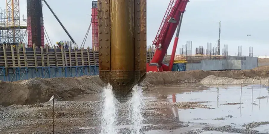
A 130 kW electric vibroflot hanging from a crawler crane looks dramatic on site, but the real risk in Peterborough is what happens in the ground when the energy stops. Loose sands under the water table can liquefy if the design relative density stays below seventy percent, and we have seen foundation distress on older industrial units near the Embankment where the original ground treatment was either skipped or poorly verified. The design report must specify the target density and the hold time at each stage, because pulling the probe too fast leaves a column of untreated material that nobody sees once the stone backfill goes in. We also watch for buried activities — Peterborough's district heating pipes and Victorian brick culverts criss-cross the city centre in ways that as-built drawings rarely capture, and a vibroflot does not forgive a collision. A thorough service clearance survey and a CAT scan before the rig moves in are non-negotiable parts of the method statement we prepare.
Regulatory framework
BS EN 1997-1:2004 — Geotechnical design, general rules, BS EN 1997-2:2007 — Ground investigation and testing, BS 5930:2015+A1:2020 — Code of practice for ground investigations, ICE Specification for Ground Treatment (2nd edition)
Linked services
Feasibility and design report
Evaluation of grain-size curves and CPT data to confirm vibro suitability, followed by detailed compaction point layout, target relative density specification, and settlement estimates under service loads.
On-site verification and testing supervision
Supervision of the trial compaction area, pre- and post-treatment CPT comparison, zone load testing to BS 1377, and sign-off documentation for building control and warranty providers.
Typical parameters
Q&A
What does vibrocompaction design cost for a typical Peterborough industrial unit?
For a standard warehouse footprint of around 2,000 to 4,000 square metres on treatable sands, the design package including feasibility assessment, compaction point layout, and on-site verification typically falls between £1,040 and £4,450 depending on the complexity of the ground profile and the number of verification tests required.
How do you decide if the ground at my site is suitable for vibrocompaction?
We look at the fines content first — anything above about fifteen percent passing the 63-micron sieve generally rules out vibrocompaction and points towards stone columns instead. The grain-size curve from a proper laboratory test is the single most important piece of data, followed by CPT tip resistance and the groundwater level.
How long does the design process take before the rig can mobilise?
Once we have the ground investigation data in hand, the feasibility assessment and preliminary design usually take five to seven working days. The final method statement and verification plan follow within another week, assuming no major revisions after the trial compaction area is tested.
Do you handle the Section 61 consent for noise and vibration with Peterborough City Council?
We prepare the technical appendix describing predicted vibration levels and mitigation measures, which your contractor can submit as part of the Section 61 prior consent application. The Council's environmental health team is familiar with vibro work and generally wants to see monitoring point locations and trigger levels before they approve the hours of operation.